Cutting tool reference
Chamfer Mills
Angle selection, flute count, coatings, and cutting parameters for the tool that breaks more edges than any other in the shop. Written for machinists and manufacturing engineers who need the chamfer to measure the same on part one and part four hundred.
- Common angles
- 60 – 120°
- Flute counts
- 1 – 6
- End styles
- Single / double
The basics
What a chamfer mill actually is
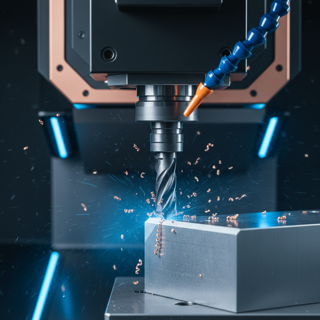
A chamfer mill is a rotary cutting tool whose cutting edges lie on a cone rather than on a cylinder. Instead of removing material with the side of a straight flute, it removes it with an angled flank, which is what produces the flat, angled face we call a chamfer.
The important consequence of that cone geometry is that the tool has no single cutting diameter. Near the tip, the diameter is small and the surface speed is low. Farther out along the flank, the diameter grows and the surface speed rises with it. Where you position the tool in Z therefore changes both the width of the chamfer and the speed at which the edge is actually cutting. Most chamfering problems trace back to that one fact.
Modern chamfer mills are usually solid carbide, though high speed steel remains common in lower-volume shops and on manual machines. Carbide holds an edge far longer at temperature and tolerates the higher surface speeds that produce a clean chamfer, while HSS is more forgiving of interrupted cuts, marginal rigidity, and the occasional crash.
Most chamfer mills carry a small flat or a slight radius at the tip instead of a true point. That flat keeps the fragile apex out of the cut, and it gives the tool somewhere to put the load when a program drives it a few thousandths deeper than intended. It also means the theoretical cone apex sits slightly below the physical tip, which matters when you calculate chamfer width from Z depth.
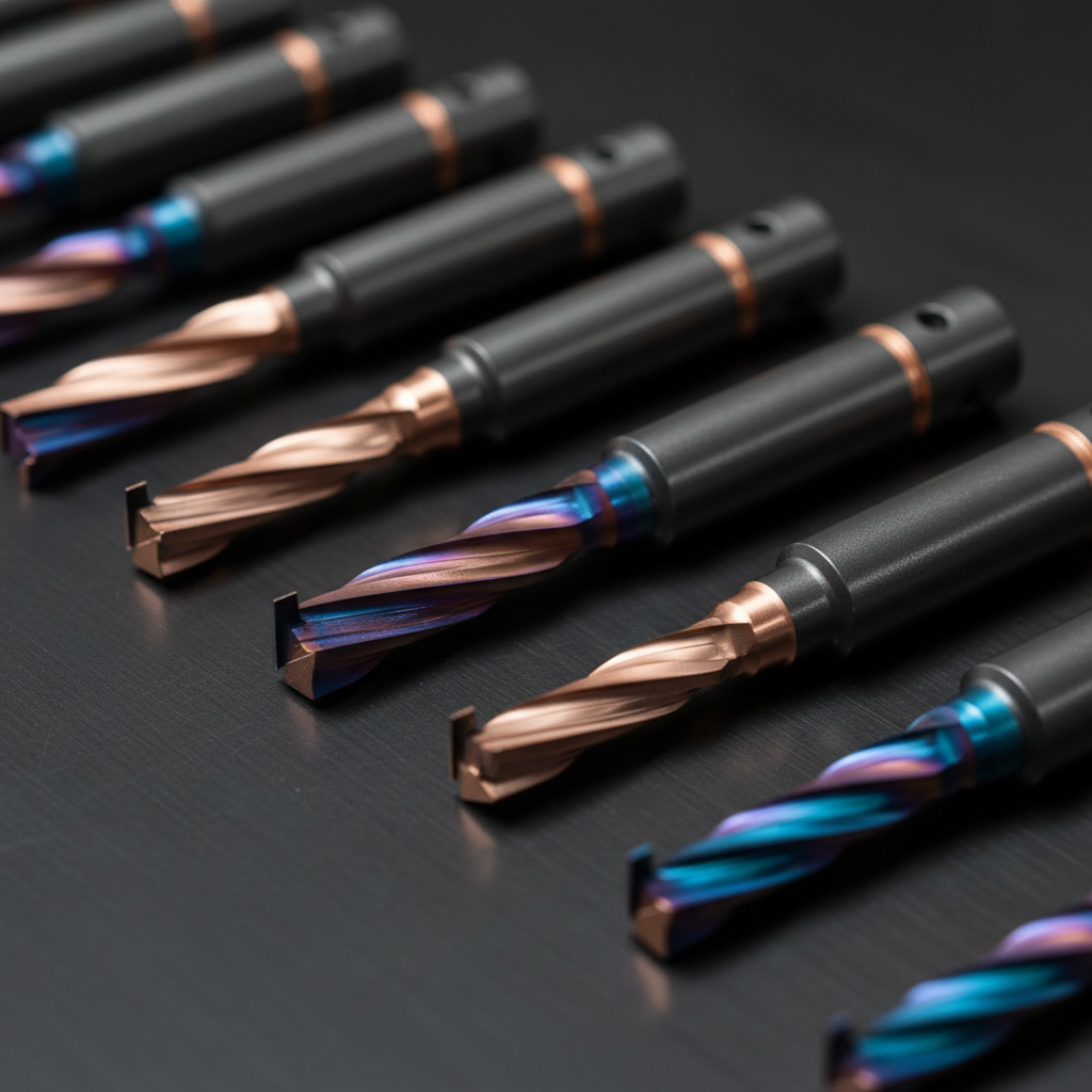
Chamfer mills are stocked by included angle, tip diameter, shank diameter, flute count, and maximum chamfer width. All five matter when ordering.
Chamfer mill vs. spot drill vs. countersink vs. deburring tool
These four tools all produce an angled surface, and they are routinely substituted for one another. They are not interchangeable, and knowing which job each one is built for prevents most of the finish and fit problems that follow.
| Tool | Geometry | Cutting motion | Best at |
|---|---|---|---|
| Chamfer mill | Angled peripheral cutting edges on a milling body, usually with a small flat or radius at the tip rather than a true point. | Cuts on the flank while traveling along an edge, contouring a bore, or plunging. | Repeatable chamfers of a controlled width on 2D edges, hole entries, and contoured profiles. |
| Spot drill | Short, stiff, pointed drill body with a defined point angle (90°, 120°, and 140° are common). | Plunge only, on the hole centerline. | Establishing an accurate hole location and a starting cone for the drill that follows. |
| Countersink | Conical body with a fastener-specific included angle, often with a single relieved flute or multiple flutes. | Plunge on the hole centerline, typically at low RPM. | Producing a fastener seat so a flat head sits flush with the surface. |
| Hand or spring deburring tool | Swiveling blade or scraper carried in a hand holder or a spring-loaded machine holder. | Dragged along the edge, following the contour under spring pressure. | Knocking down burrs where no dimensioned chamfer is required, or on edges a rigid tool cannot follow. |
Angle selection
Included angles and where each one belongs
Five included angles cover nearly all industrial chamfering: 60°, 82°, 90°, 100°, and 120°. Each exists because of a specific requirement, and picking by habit rather than by requirement is how a fastener ends up sitting proud of the surface.
Included angle is not the angle on the print
Tooling catalogs specify the included angle, which is the full angle measured across the cone, apex to flank to flank. Drawings usually specify the angle of the chamfer face relative to one of the part surfaces, which is half that number.
So a print that reads 0.030 × 45° is cut with a 90° included angle chamfer mill, not a 45° one. A 60° included angle tool produces a 30° face. An 82° tool produces a 41° face.
face angle = included angle ÷ 2
A minority of suppliers list the same tools by the per-side angle. Confirm which convention a catalog uses before ordering, because both a “45° chamfer mill” and a “90° chamfer mill” may describe the identical tool.

| Included angle | Face angle | Typical use | Watch for |
|---|---|---|---|
| 60° | 30° | Weld preparation, thread lead-ins, and light deburring where a shallow, wide-sweeping cut is wanted. The narrow point also reaches into tight internal corners a blunter tool cannot enter. | Produces a long chamfer face for a given depth of cut, so watch tool deflection on the unsupported point. |
| 82° | 41° | Countersinking for inch-series flat head screws, which are specified at an 82° included angle in ASME B18.6.3. Used when the chamfer has to seat a fastener head flush, not just break an edge. | Do not substitute a 90° tool on an 82° fastener seat. The head will contact on its outer edge and can loosen or crack. |
| 90° | 45° | The workhorse. General edge breaking, print callouts written as 45°, deburring, hole chamfers, and spotting. If a shop stocks one chamfer angle, this is it. | This is where the naming confusion bites: a print asking for a 45° chamfer is cut with a 90° included angle tool. |
| 100° | 50° | Flush-head aerospace fasteners and rivets specified at a 100° included angle. Common in airframe, defense, and structural sheet work. | Usually paired with tight depth control, since the seat depth drives fastener flushness on thin skins. |
| 120° | 60° | Spotting ahead of split-point drills, shallow hole lead-ins, and thin material where a steeper chamfer would break through the wall. | For spotting, the spot angle should be equal to or blunter than the drill point angle so the drill's chisel edge lands first and the outer corners do not chip. |
Tool geometry
Flute count, and single versus double end
Flute count is a chip evacuation decision first and a finish decision second. End configuration is a cost and clearance decision. Both are easy to get wrong by copying whatever the last job used.
1 flute
Aluminum, copper, plastics, and very small chamfers
Maximum chip room and the largest gullet for gummy material. Single-flute chamfer tools also let a small tip diameter reach into features where a multi-flute body would not fit.
2 – 3 flutes
Aluminum and other non-ferrous alloys, general shop use
A practical balance of chip evacuation and edge count. Three flutes gives a noticeably better finish than two without choking chips in soft, sticky material.
4 flutes
Carbon and alloy steels, cast iron, general steel work
The default for ferrous material. More edges in the cut per revolution means higher table feed at a sane chip load, and the body is stiffer than a two-flute equivalent.
5 – 6 flutes
Stainless, tool steel, hardened material, finish passes
The lightest chip load per tooth and the smoothest finish. Chip room is small, so keep engagement light and make sure chips are being cleared, not recut.
Single end vs. double end
Double end
Cutting geometry on both ends of one blank. Two usable ends means a lower cost per cutting edge, which adds up in production. The tradeoffs: the unused end sits inside the holder and can be damaged if it bottoms out, the tool cannot be necked down for reach, and overall length is fixed by the need to grip the middle safely.
Single end
One working end, and everything behind it is available for design. That allows reduced necks, long-reach bodies, larger maximum chamfer widths, and shorter overall lengths for rigidity. It is the right call when clearance around the cut is tight or the chamfer is large.
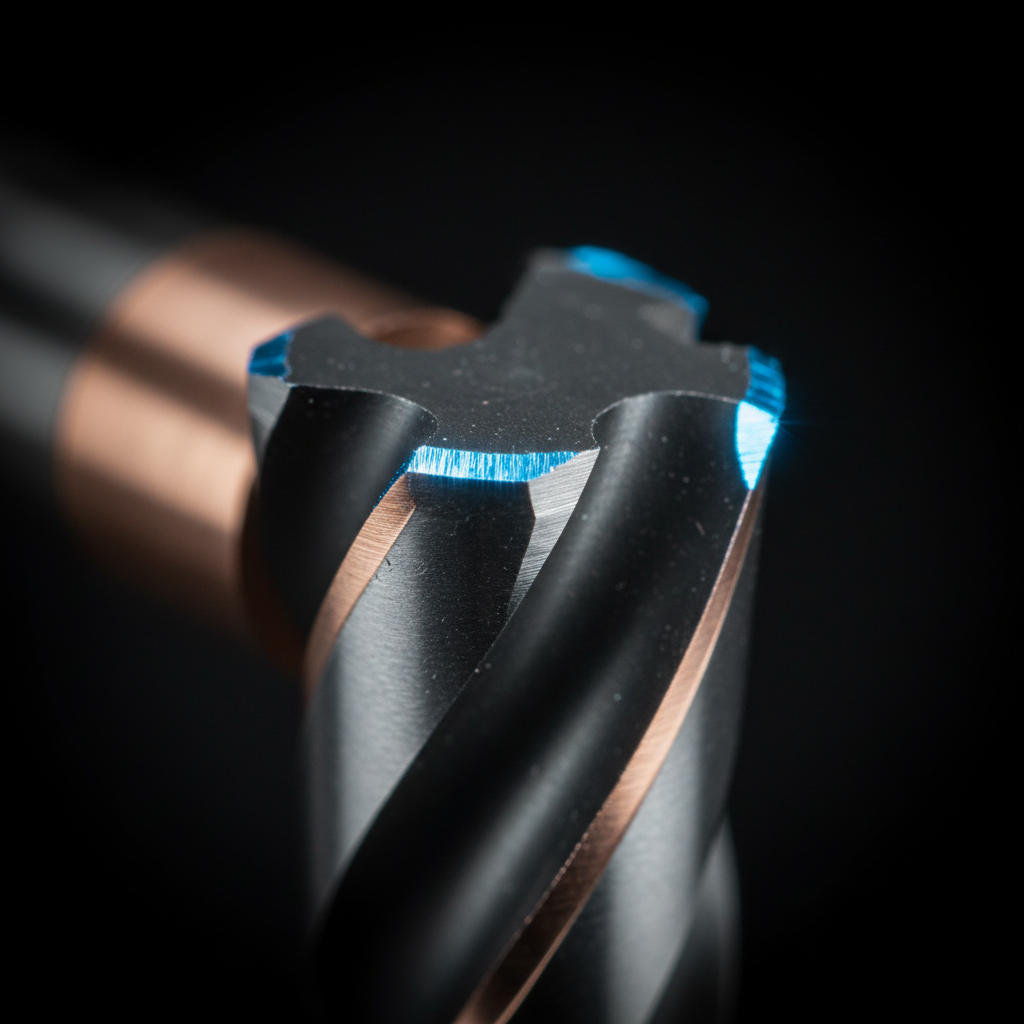
A note on maximum chamfer width
Every chamfer mill has a maximum chamfer width, set by the usable length of the angled cutting edge. Exceeding it in one pass loads the tip and the transition to the body at the same time. Larger chamfers are taken in stepped passes or with a larger tool.
Coatings
Matching the coating to the workpiece
Coating selection follows the workpiece material, not the tool. The wrong coating does not simply underperform: an aluminum-bearing coating on aluminum invites the exact failure mode you are trying to avoid.
TiAlN
Violet to bronzeCarbon steel, alloy steel, cast iron, and general ferrous work at moderate to high speed.
Forms a hard aluminum-oxide layer as cutting heat rises, which slows crater and flank wear. It performs best when it is allowed to run hot, so it pairs well with high surface speed and consistent coolant, not with intermittent flooding.
AlTiN
Dark charcoal to blackHardened steels, high-temperature alloys, dry and minimum-quantity lubrication cutting.
Higher aluminum content than TiAlN gives more oxidation resistance at elevated temperature, which is what you want when the cutting zone is genuinely hot and coolant cannot reach it.
ZrN
Pale goldAluminum, brass, copper, and other non-ferrous alloys.
Low friction and low affinity for aluminum, so it resists built-up edge and galling on gummy material where an aluminum-bearing coating would weld chips to the flank.
Uncoated, bright polished
Carbide greyAluminum, plastics, and any material where a sharp, keen edge matters more than heat resistance.
A polished flute is the smoothest chip path available, and an uncoated edge can be ground sharper than a coated one because there is no film thickness rounding the edge.
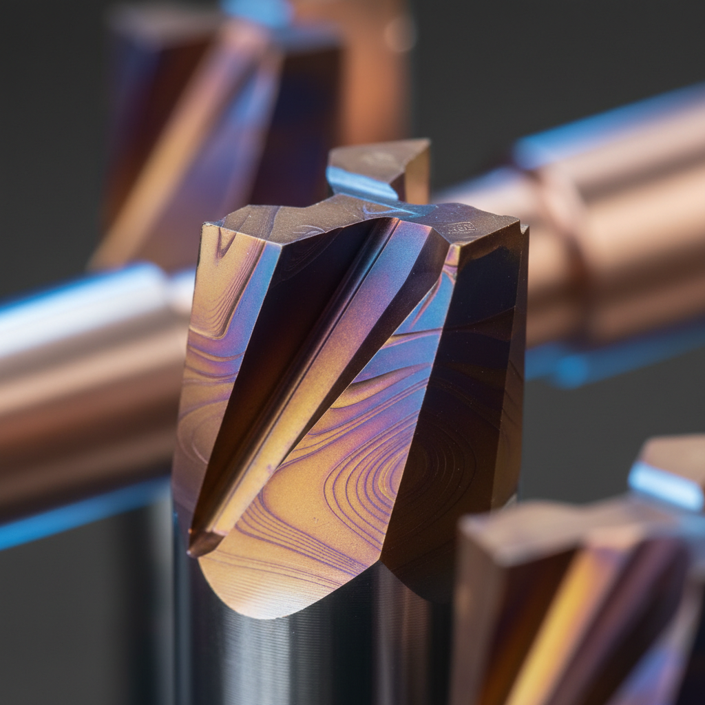
Coating color is a useful visual shorthand on the shelf, but it is not a specification. Two suppliers can apply visibly different shades of the same coating family. Read the label.
Cutting parameters
Speeds and feeds start with effective diameter
A chamfer mill is the one common milling tool where plugging the catalog diameter into an RPM formula gives an answer that is simply wrong. The cut happens on a cone, so the engaged diameter depends on how deep the tool is running.
The two calculations that matter
1. Effective cutting diameter
Where D_tip is the flat or radius diameter at the point, h is the axial depth of engagement, and A is the included angle. Use the largest diameter actually in the cut, since that is where surface speed peaks and where the tool is most likely to be over-sped.
2. Spindle speed and table feed
Inch units. For metric, use RPM = (1000 × Vc) ÷ (π × D_eff).
Practical starting points
- Begin with the tool manufacturer's published surface speed and chip load for your material and coating. Those numbers are generated on their tools with their geometry, and they are a better anchor than a generic table.
- Chamfering is a light radial engagement operation, so chip thinning applies. The programmed feed can often be raised above the nominal chip load figure, but only after the cut is proven stable.
- Never let the feed drop so low that the edge rubs instead of cutting. Rubbing generates heat without removing material, work hardens the surface ahead of the tool, and is the fastest way to kill a chamfer mill in stainless.
- Slow the feed through corners and at direction changes, or program a lead-in arc. Full feed into a corner deflects the tool and leaves a wider chamfer exactly where the eye lands.
- Vary the Z depth slightly from job to job so the wear band moves along the cutting edge instead of concentrating in one strip.
Rigidity beats numbers. Chamfer mills are short, but they are frequently run at long stickout to clear fixtures. Before adjusting speed or feed to cure a problem, pull the tool up into the holder as far as the cut allows. It is free, it is instant, and it fixes more chamfering complaints than any parameter change.
Toolpath
Chamfering strategy on a CNC machine
How the toolpath engages the cone determines finish quality, chamfer consistency, and how many parts the tool survives. Three approaches cover almost all work.
Straight contour pass on an outside edge
The tool is set at a fixed Z so that the flank of the cone intersects the workpiece edge by the required chamfer width, then driven along the profile with the same offset logic as an end mill. Climb mill the pass. Keep the tip clear of the material so the cut stays out on the flank where surface speed is highest, and confirm the chamfer width on the first part with a gauge rather than trusting the calculation alone.
Circular or helical interpolation on holes
For any hole the tool fits inside with clearance, interpolate. The chamfer diameter becomes a function of the path radius, so one tool covers a whole range of hole sizes without a Z change, and the cut lands on the flank all the way around. Lead in on an arc rather than plunging to the start point, and lead out the same way so the tool does not dwell and leave a witness mark where the path closes.
Plunge chamfering
Fast, simple, and the right answer on small holes where the tool cannot fit inside, and on high-volume work where the tool angle already matches the required seat. The limitations are real: chamfer diameter depends entirely on Z depth, the tip region is in the cut where surface speed approaches zero, and any variation in surface height shows up directly as a variation in chamfer size.
Large chamfers: step, do not force
When the required chamfer approaches or exceeds the tool's maximum width, break it into stepped passes. Offset in X and Y and step down in Z so each pass removes a manageable slice of the triangle, and leave a light finishing pass at final position. One heavy pass concentrates the entire load on the weakest part of the tool.

Reaching the far side
A chamfer on the underside of a through hole cannot be reached from the top with a standard tool. A back chamfer tool, which passes through the hole and cuts on the pull-up stroke, handles it in the same setup and avoids flipping the part. Where the geometry does not allow one, a spring-loaded deburring holder following the hole contour is the usual fallback, though it produces a broken edge rather than a dimensioned chamfer.

Material notes
What changes when the workpiece changes
The same tool geometry behaves very differently across the four material families that dominate machined parts. These are the practical differences that show up at the machine.
Aluminum
Run fast with a sharp, polished or ZrN-coated tool and few flutes. Chips must leave the cut, so use air blast or a lubricant that keeps material from welding to the flank. Built-up edge, not wear, is what usually ruins the finish.
Carbon and alloy steel
A four-flute TiAlN tool at moderate surface speed covers most work. Keep the feed high enough that the edge is cutting rather than rubbing, since rubbing generates heat without removing material and work hardens the surface ahead of the tool.
Stainless steel
Assume it work hardens. Never dwell, never let the tool spring back and rub, and keep the feed constant through corners. Drop surface speed relative to carbon steel, raise chip load slightly, and use flood coolant aimed at the cutting zone.
Titanium
Low surface speed, sharp positive geometry, and as much coolant pressure as the machine can deliver. Heat concentrates in a small zone at the edge because titanium conducts it poorly, so the tool takes the thermal load. Continuous engagement without dwelling is the goal.
Process troubleshooting
When the chamfer comes out wrong
Five symptoms account for most chamfering complaints. In each case the cause is usually mechanical, and the fix is usually cheaper than a new tool.
Chatter along the chamfer
Likely causes: Excess tool stickout, too many flutes engaged at once, a worn edge, marginal workholding, or a spindle speed sitting on a resonant frequency of the setup.
What to do: Shorten the tool in the holder before changing anything else, then change RPM in meaningful steps rather than small ones to move off the resonant point. Increasing feed per tooth often quiets a chattering chamfer pass because it forces the edge to cut instead of rub. Check that the part is clamped near the edge being cut, not just at the far end.
Poor or torn edge finish
Likely causes: The tip of the tool is in the cut, where surface speed approaches zero, or the edge is dull, or built-up edge is smearing the flank.
What to do: Shift the tool in Z so the cut happens on the flank of the cone, well away from the point. Climb mill the finishing pass. On aluminum, switch to a sharper uncoated or ZrN tool and improve chip clearing before adjusting speed.
Chamfer width varies along the edge
Likely causes: Z-height variation across the part, an out-of-flat or unsupported workpiece, tool deflection, or machine backlash on the finishing direction.
What to do: Probe or indicate the surface before assuming the tool is the problem. Support the part underneath the edge being cut. Take a spring pass at the same Z to remove deflection error, and keep the finishing pass in one consistent direction.
Rapid tool wear at one band on the flank
Likely causes: The same narrow strip of the cutting edge is doing all the work every pass, and heat is concentrating there.
What to do: Vary the Z depth slightly between parts or between passes so the wear spreads across the cutting edge. This alone can multiply the usable life of a chamfer mill, and it costs nothing but a line of code.
Burr pushed to the far side of the edge
Likely causes: Material is being displaced rather than sheared, usually from a dull edge, a light chip load, or cutting direction pushing material off the unsupported side.
What to do: Increase chip load, sharpen or replace the tool, and reverse the direction of the final pass so material is pushed toward supported stock. On hole edges, a back chamfer tool addresses the far side directly instead of trying to reach it from the top.

Measure it
Chamfer width is easy to eyeball and easy to get wrong. Optical comparators, chamfer gauges, and vision systems all give a repeatable number. On a new program, check the first part before the second one is cut, not after the run.
FAQ
Chamfer mill questions machinists actually ask
Is a 45 degree chamfer mill the same as a 90 degree chamfer mill?
In practice, yes, and this is the single most common ordering mistake in chamfering. Tool catalogs list the included angle, which is the full angle of the cone measured across the tip. A 90° included angle tool leaves a face 45° from the workpiece surface. So when a print calls for a 45° chamfer, order a 90° chamfer mill. Some suppliers list the same tool as 45° per side, which is why it pays to read whether the number refers to the included angle or the angle per side before you buy.
Can I use a spot drill to chamfer holes instead?
You can, and plenty of shops do for small chamfers on hole entries. The tradeoffs are that a spot drill has a point, so the chamfer diameter you get depends entirely on plunge depth, and it only works on the hole centerline. A chamfer mill can interpolate around the bore, which means one tool covers a wide range of hole sizes and the chamfer width is controlled by the toolpath radius rather than by Z depth alone.
What is the difference between a chamfer mill and a countersink?
A countersink exists to create a seat so a flat-head fastener finishes flush with the surface, so its angle matches a fastener standard and it is almost always plunged on centerline at low RPM. A chamfer mill is a milling tool: it cuts on its flank while moving along a path, so it handles straight edges, contours, and bore interpolation as well as plunging. Where the two overlap, the countersink usually wins on fastener seats and the chamfer mill wins on everything else.
How do I calculate RPM for a chamfer mill?
Use the effective diameter, not the shank or the tip diameter. The cut happens somewhere along the cone, so the diameter actually engaged is the tip diameter plus twice the radial projection of the engaged edge. For an included angle A and an axial engagement depth h, that is D_eff = D_tip + 2 × h × tan(A ÷ 2). Then RPM = (3.82 × SFM) ÷ D_eff for inch units. Skipping this step is why chamfer mills often run far off the intended surface speed.
Should I chamfer holes by plunging or by interpolating?
Interpolate whenever the hole is large enough for the tool to fit inside it with clearance. Circular or helical interpolation puts the cut on the flank of the tool where surface speed is highest, gives a consistent chamfer all the way around, and lets a single tool produce many different chamfer diameters by changing the path radius. Plunging is faster on small holes and on high-volume parts where the tool angle already matches the required seat.
Single end or double end?
Double-end tools carry a cutting geometry on both ends, so one tool holds two usable ends and the cost per edge drops. The catch is that the second end sits in the holder while the first is in use, the tool has to be long enough to be gripped safely, and you cannot reduce the neck for reach. Single-end tools allow necked and long-reach designs, larger maximum chamfer widths, and are the practical choice when clearance around the cut is tight.
How many flutes should a chamfer mill have?
Match flute count to chip evacuation, not to the finish you wish you had. Aluminum and other gummy materials want one to three flutes so chips can escape. Steel and cast iron run well on four. Stainless, tool steel, and finishing passes benefit from five or six, provided engagement stays light enough that chips are not being recut in a small gullet.
Why does my chamfer look burnished instead of cut?
Almost always because the cut is happening too close to the point of the tool. Surface speed falls toward zero as the diameter approaches zero, so the tip does not cut, it rubs. Move the tool in Z so the engaged portion of the cone sits well out on the flank, and confirm the tool has not been driven so deep that the flat at the tip is bottoming on the workpiece.
What coating should I run on aluminum?
Something that does not contain aluminum. ZrN, a polished uncoated carbide, or a diamond-family coating all resist the built-up edge that ruins aluminum finishes. Aluminum-bearing coatings such as TiAlN and AlTiN are built for heat resistance in ferrous work and have an affinity for aluminum workpiece material, which is exactly the wrong property here.
Can chamfer mills cut a chamfer larger than the tool's stated capacity?
Not in a single pass. Every chamfer mill has a maximum chamfer width set by the length of the angled cutting edge between the tip and the point where the body transitions. Beyond that, take stepped passes, offsetting the tool in X and Y and stepping down in Z so each pass removes a manageable slice, or move to a larger tool. Trying to take an oversized chamfer in one pass loads the unsupported point and is a common way to snap the tip.
Get a Quote
Working through a chamfering problem?
Send the details of the job and we will point you toward the right angle, geometry, and approach. Tooling questions, sourcing questions, and questions about this site are all welcome.
- Angle and geometry selection for a specific print callout
- Diagnosing chatter, inconsistent width, or short tool life
- Coating and flute count choices for a new material
- Acquiring this domain — see the details
ChamferMills.com is available for acquisition. The exact-match domain and this site transfer together.
Acquisition details